TWS earbuds
Ergonomic chambers, charging-case interfaces and acoustic rear volumes — revisions need no tooling, and multiple parts per build keep the batch consistent.
- Chamber + case fit
- Minimum wall thickness 0.6 mm
- Revisions are a file change
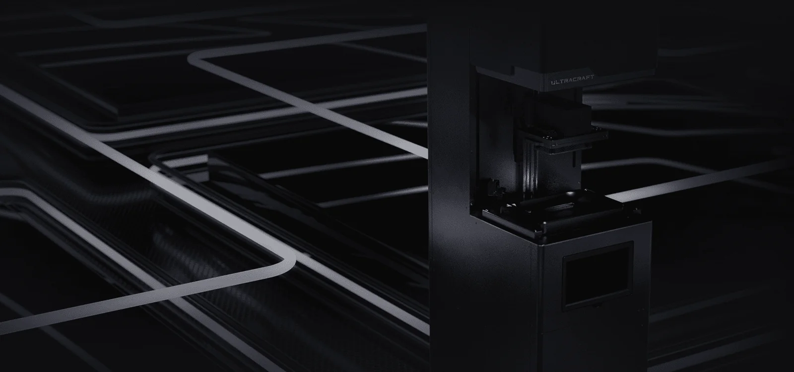
DLP Additive Manufacturing · Precision Hearables
DLP photopolymer service with 25 μm layers and 22 μm projection pixels. From ear-impression scans to finished shells, structural parts and acoustic chambers — 10–500 units formed in a single build, first articles in 48 hours.
Positioning
Injection moulding needs tooling, CNC needs toolpath planning, and every structural revision restarts a cost and lead-time cycle. In hearables — small chambers, dense structures, fast iteration — the process often decides before the design does.
DLP reverses that order: chambers, sound tubes and assembly features are formed in one piece, revisions require only a new file, and 10 units follow the same precision standard as 500.
Our process optimisation is dedicated to hearables: dimensional tolerance, tube bore, snap-fit clearance and skin-contact safety each map to a defined material and post-processing route.
Application scenarios
TWS prioritises fit and batch consistency, HiFi prioritises acoustic structure and internal volume, hearing aids prioritise contact safety, and wearable devices prioritise sandwich structures and cable routing.
Ergonomic chambers, charging-case interfaces and acoustic rear volumes — revisions need no tooling, and multiple parts per build keep the batch consistent.
Multi-driver chambers, crossover layout and labyrinth tubes formed in one piece; clear parts make internal structure directly visible.
Shell surfaces rebuilt from ear-impression data with left and right modelled separately; biocompatible options for contact parts.
Sandwich structures, cable channels and sensor mounts formed in one piece for structural validation and small-batch trial production.
Manufacturing capability
We optimise exclusively for hearables and acoustic devices: chamber dimensions, tube bore, snap-fit clearance and contact-part safety each have a matched material and post-processing route.
Shell geometry is rebuilt from ear-impression scans or intraoral scans, then fitted with balanced-armature drivers, crossover layout and tube routing. One-piece forming removes assembly error.
Headbands, cup frames, sliders, hinges and decorative panels — thin-wall ribs and snap features formed in one piece, eliminating multi-part assembly.
Cavity and sound path are formed as one part, removing lot-to-lot variation from bond lines. Damper seats, pressure-relief ports and multi-tube splits are supported.
High-precision masters are used to cast silicone tips, sleeves and small-batch soft parts, transferring surface detail directly to the finished component.
First articles in 24–48 hours for assembly checks, fit testing and acoustic tuning; once the revision is approved, the same process scales to 10–500 units.
01 / Form design
Shell models are rebuilt from impression or intraoral scans, with one-piece forming reducing assembly error. Form no longer compromises to the process — fit and appearance can both hold.
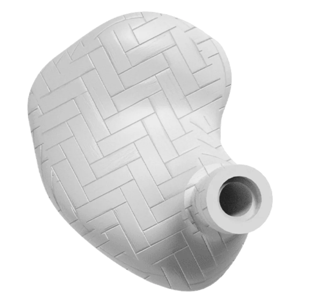
02 / Structural forming
Chambers, sound tubes and driver mounts are formed in one piece, removing lot-to-lot variation from bond lines. Damper seats, relief ports and multi-tube splits are supported.
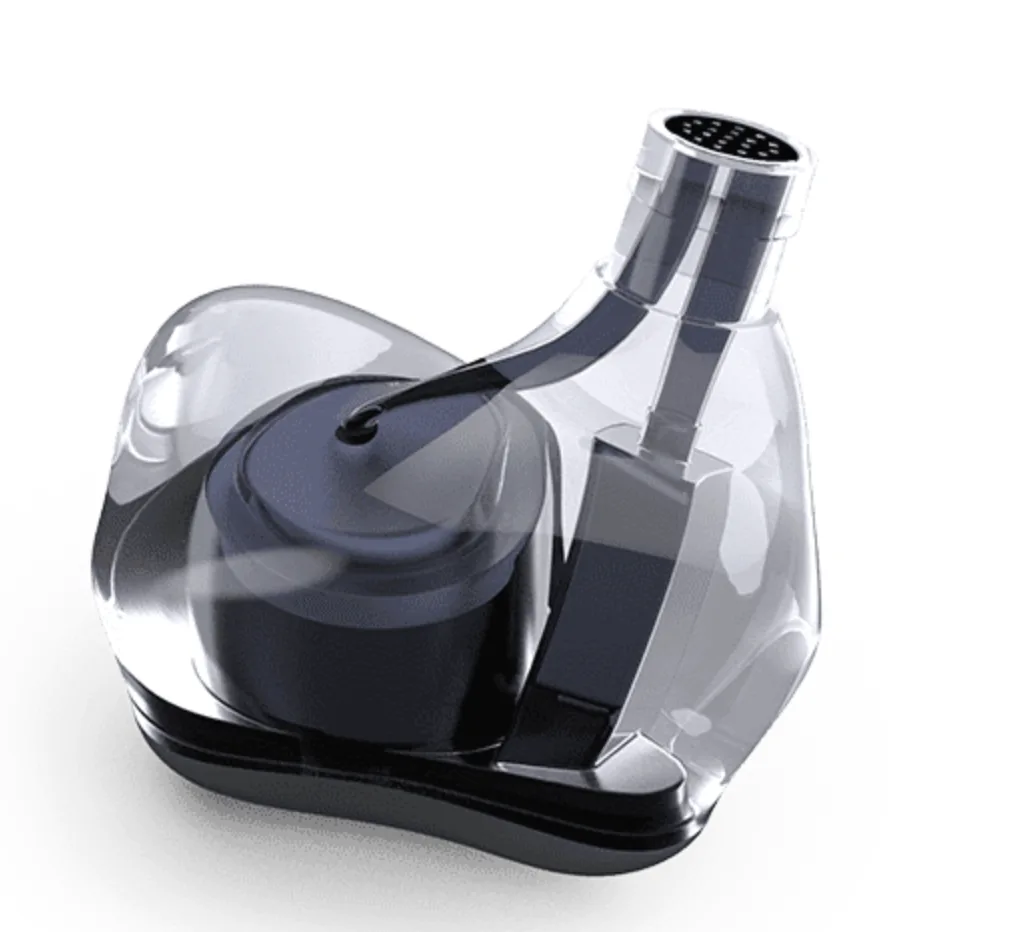
03 / Accuracy
Both are photopolymer processes, but area-exposure DLP and laser-scanning SLA perform very differently on small-batch hearables parts. Whole-layer exposure cures every part in the build at once.
| Item | DLP photopolymer (in-house) | Laser SLA | FDM extrusion |
|---|---|---|---|
| Forming method | Whole-layer exposure | Laser point scanning | Molten extrusion line |
| Minimum layer height | 25 μm | 25 μm | 100 μm |
| XY detail | 22 μm pixel | 80–140 μm spot | 400 μm nozzle |
| Small-batch efficiency | High — whole plate cures together | Medium — point-by-point scanning | Low — part-by-part deposition |
| Surface quality | Fine — layer lines nearly invisible | Fine | Visible layer lines |
| Best suited to | Small hearables parts, fine features, 10–500 units | Large, high-precision single parts | Large functional prototypes |
For parts over 100 mm or cosmetic parts with extreme surface requirements, we recommend another process rather than forcing DLP.
04 / Materials
Hearables parts hinge on contact safety, dimensional stability and acoustic performance. The table lists measured ranges for common materials; the exact grade and certification documents are confirmed per application before ordering.
Dimensionally stable, sharp detail
Impact resistant, snap features flex
For skin / ear-canal contact
High rigidity, low creep
Transparent after polishing, internals visible
Low ash, investment castable
Values are typical for common grades and vary with batch and post-processing. For ear-canal contact parts, describe the use case and we will specify a grade with the corresponding biocompatibility documentation.
05 / Surface finishing
The finishing tier follows the part's final use. Further right means a surface closer to a finished cosmetic part, with a corresponding increase in lead time.
Can be sanded / polished
Can be hand painted
Can proceed to automated painting
Ready for assembly
Photopolymer parts still show fine layer lines on curved surfaces. The standard route is sanding plus blasting for a uniform matte finish; clear parts add step sanding and polishing. Polishing is manual work and is itemised in the quote.
Process photos
Whole-layer exposure cures every part in the build at once. Below are plate layout, forming, chamber and modelling examples.
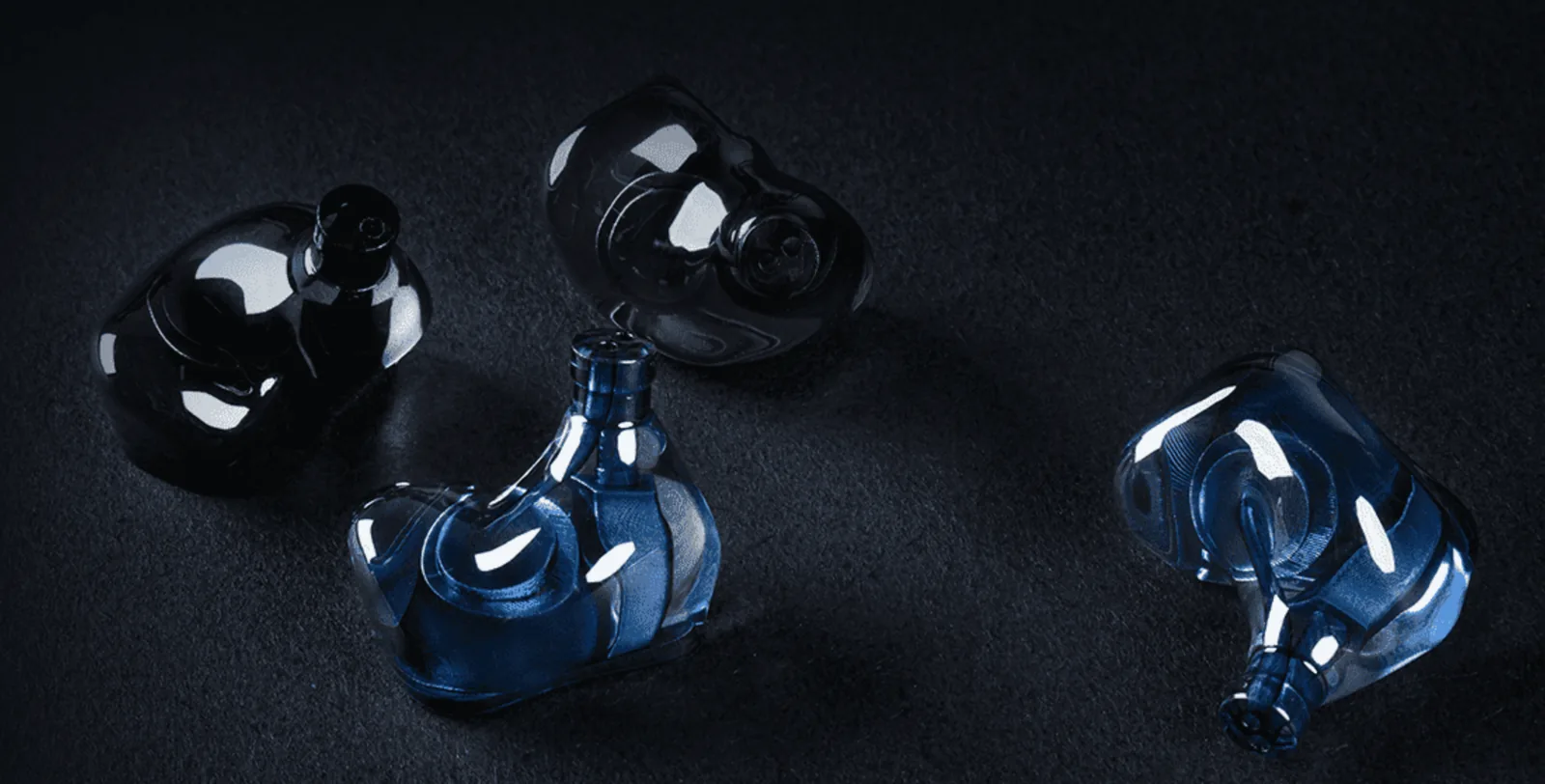
Process
Each step has a defined parameter range and delivery checkpoint, and batch orders ship with lot, material and inspection records.
Printability is checked first: wall thickness, normals, non-manifold edges, minimum features and assembly clearance. Issues are listed with recommendations.
Orientation follows load direction, critical dimensions and cosmetic faces; support contacts avoid mating and visible faces.
Layer height and anti-aliasing follow feature size, with exposure allocated per cross-section to compensate shrinkage.
A 405 nm engine projects the full cross-section onto the vat floor, curing every part in the build at once.
Two-stage cleaning: soak to dissolve residual resin, then brief ultrasonics for fine holes and tube bores.
Measured post-cure at the wavelength matched to the resin, balancing surface dryness against mechanical properties.
Supports are cut and sanded through successive grits, with mating faces finished to assembly feel; clear parts add polishing.
Critical dimensions are sampled or fully inspected against the drawing; appearance is compared with the approved sample.
Process scenarios
From equipment and plate layout to chamber structure, surface finishing and custom modelling, each stage has its own process choices. Shipped-product case studies are on the case studies page.
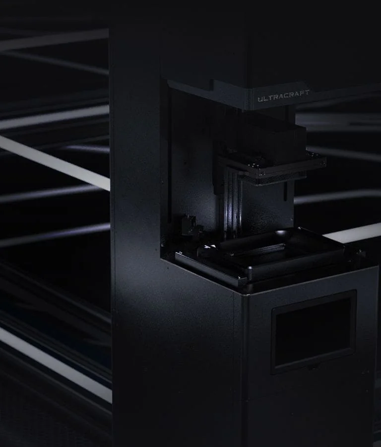
Whole-layer exposure cures every part in the build together; small batches need no tooling.
Driver mounts and sound tubes are integrated into one shell, so assembly needs only a single bonding step.
Sanding, blasting, polishing or coating are selected by application; clear parts can add polishing for transparency.
Shell surfaces are rebuilt from impression or intraoral scan data, modelled separately for left and right and delivered as a pair.
06 / Design service
We handle impression scan data, structural modelling, tolerance confirmation and first-article trial fitting. First articles ship in 24–48 hours for assembly validation and acoustic tuning; once the revision is approved the same process scales to 10–500 units.
Scan intake and cleanup
Chamber, tubes, assembly features
Sample validation in 24–48 h
Scale to 10–500 units on the same process
If 2D drawings are needed to confirm tolerances, or material certification is required, state it with the order.
FAQ
Concrete methods and numbers from real projects beat adjectives.
For parts contacting skin or the ear canal we recommend a medical-grade resin intended for biocompatible use, with the contact area and wear duration stated on the order. We supply batch and certification documents; final compliance depends on your target market's regulations.
XY projection pixels are 22 μm, with reliable detail around 0.15 mm; minimum through-hole 0.4 mm and minimum stable wall 0.6 mm. Below these values parts are not impossible, but yield and consistency drop, so we validate with a small sample first.
Standard parts ship a first article in 24–48 hours depending on height and finishing; 10–500 unit batches typically take 3–7 business days. Rush orders can be slotted in.
STEP or 3MF preferred (keeps solids and assembly data), then STL and OBJ. Include 2D drawings or notes for assembly relationships, tolerances or surface requirements.
25 μm gives finer layer lines and smoother curves, but doubles the layer count and print time. For most hearables parts 50 μm balances detail against efficiency; reserve 25 μm for sound tubes and mating faces sensitive to surface continuity.
Photopolymer parts still show fine layer lines on curved surfaces. The standard route is sanding plus blasting for a uniform matte finish; clear parts add step sanding and polishing. Polishing is manual work and is itemised in the quote.
Pricing combines material, layer height, finishing tier and quantity. You can validate assembly and fit with a single part or small batch, then scale on the same process; no tooling-type fees are charged again after first-article approval.
News and insights
Concrete methods and numbers from real projects beat adjectives.
 Case Studies
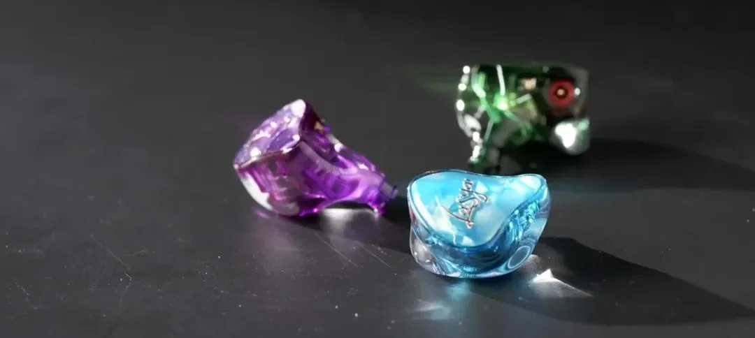
Six balanced-armature drivers, a crossover board and resistors inside one chamber — without losing the unibody look.
 Case Studies
Left/right consistency, surface quality and colouring were the client's three priorities in this project.
 Process guide
Is 25 μm always better? Which parts justify high resolution, and where 75 μm is more cost-effective.
Contact us
Send the part's application, quantity and accuracy requirements, and we will reply with recommended material, finishing tier and lead time.