DLP 3D Printing
for Hearables

DLP solutions for TWS earbuds, custom in-ear monitors, hearing aids and hearing protection. Chambers, sound tubes and driver mounts are formed in one part — no draft angles and no tooling — running the same parameters from appearance validation to 10–500 unit batches.

  • 22 μmXY projection pixel
  • 25 μmMinimum layer height
  • ±0.03 mmFeature tolerance (≤30 mm)
  • 48 hFirst articles
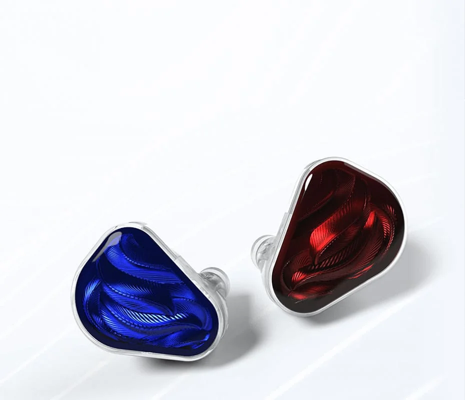
Custom in-ear monitor shape and chamber structure
Chamber and acoustic path design · structure and form formed together

Application scenarios

Four hearables categories, four process priorities

For the same kind of shell, TWS prioritises fit and batch consistency, HiFi prioritises acoustics and internal structure, and hearing aids prioritise contact safety. Different routes mean different materials, layer heights and finishing.

TWS earbuds

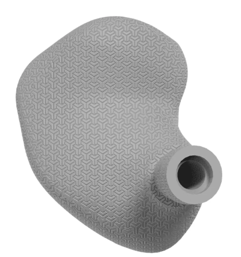
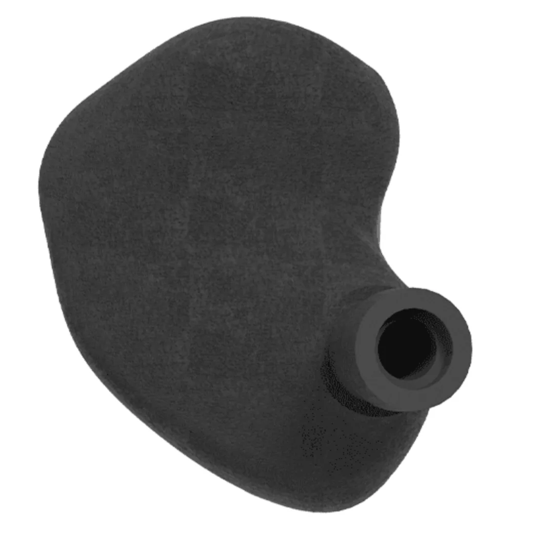
The chamber conforms to the concha and canal opening, balancing long-wear comfort with a recognisable look; case interfaces, magnet locations and contact clearances are formed with the shell.

  • Ergonomic chamber and weight tuning
  • Case location features and contact clearances
  • Cosmetic revisions without tooling; small editions are viable
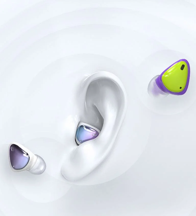
Custom in-ear / multi-driver

Multi-driver chambers, crossover mounts and labyrinth sound tubes are formed in one piece, cutting bonding steps. Clear material turns internal structure into part of the exterior.

  • 2–8 driver chambers with crossover mounts
  • Multi-way tubes, damper grooves and relief ports
  • Clear / translucent shell with optional internal colouring

Hearing aids and protection

Canal geometry is rebuilt from ear-impression scans with left and right modelled separately; contact parts use biocompatible materials with matching batch documentation.

  • Shell rebuilt from impression / intraoral scan data
  • Independent left/right modelling with difference management
  • Certification documents available for contact materials

Wearable audio devices

Sensors, batteries and PCBs must fit inside one shell. Open sandwich structures and cable channels are printed directly, so assembly order can change without tooling changes.

  • Sandwich structures and module mounts
  • Cable channels, snaps and retention features
  • Structural validation parts in 24–48 h

Capability support

Five things decide whether a shell reaches production

These five capabilities run through everything from model to finished part, and are the areas we have validated repeatedly on hearables projects.

  1. 01

    Ergonomic chambers that fit the ear

    Surfaces are rebuilt from impression or intraoral scans, with continuous transitions across the concha, tragus and canal opening so pressure spreads and long wear stays comfortable.

  2. 02

    Structural design without draft constraints

    Additive forming has no parting line or draft direction, so internal undercuts, thin-wall ribs, driver seats and threaded insert bores are built with the shell.

  3. 03

    Acoustic paths formed in one piece

    Sound tubes, damper grooves, front/rear chamber separation and pressure-relief ports are printed directly, reducing bond lines and the batch variation that assembly brings.

  4. 04

    A material set covering fit and acoustics

    Clear, translucent, tough and high-temperature resins are selected by application; for ear-canal contact parts we recommend a medical-grade material with biocompatibility documentation and a stated use case.

  5. 05

    Consistency at small-batch scale

    Whole-layer exposure cures every part in the build together. 50 units and 500 units run the same slice parameters, the same post-processing sequence and the same inspection criteria.

The above describes process capability; achievable tolerance and surface depend on part structure and finishing requirements. We run a printability assessment before any order.

Route A

TWS: turning a design revision into one print

TWS earbud chamber design
TWS earbuds · ergonomic chamber and case fit

Design freedom

No design compromises for tooling

Injection moulding forces compromises on undercuts, recesses and complex parting. DLP has no such constraint: chamber tweaks, added or removed wings, local texture and edition differences are all a file change — with no tooling cost or modification cycle.

From appearance validation to small-batch supply, one model and one post-processing standard are used — avoiding the sample-versus-production mismatch.

Recommended layer height
50 μm
Minimum stable wall
0.6 mm
Mating face tolerance
±0.05 mm
Build capacity
8–40 parts

Route B

HiFi: making acoustic structure visible

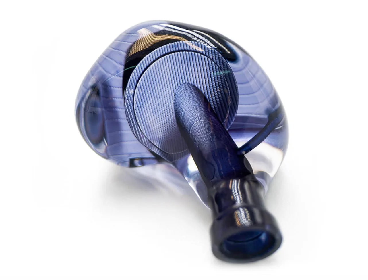
Custom HiFi in-ear monitor chamber
Custom in-ear · multi-driver chamber with integrated sound tubes

Acoustic structure

Multi-driver chamber and sound tubes in one piece

Driver seats, crossover mounts and sound tubes are integrated into one shell, so assembly needs no repeated bonding or re-alignment and tube routing stays consistent across revisions.

Sound tube bore
0.8–2.0 mm
Minimum through-hole
0.4 mm
Curve layer height
25 μm
Clear part surface
Ra ≤1.6 μm
  1. 01Impression / scan data
  2. 02Shell rebuild and driver layout
  3. 03Printing
  4. 04Fitting and post-processing
  5. 05Fit trial and delivery

Clear parts are affected by UV and sweat over time; we recommend anti-yellowing formulations and internal colouring by application, and itemise manual operations such as polishing in the quote.

Process scenarios

How three stages are handled

From plate layout and impression modelling to surface finishing, every stage affects final dimensions and appearance.

Build layout and batch production

Equipment and plate layout

Whole-layer exposure cures every part together; layout is arranged by height and projected area to improve utilisation.

  • 25–100 μmLayer height
  • 8–40 partsParts per build
  • 48 hFirst-article lead time
Ear-impression scanning and custom modelling

Ear-impression modelling

Shell surfaces are rebuilt from ear-impression or intraoral scans, modelled separately for left and right and delivered as a pair.

  • 2 piecesIndependent L/R modelling
  • 3 optionsSources
  • 48 hFirst-article delivery
Hearable housing surface finishing and coating

Surface finishing and coating

Sanding, blasting, polishing or coating are selected by application; clear parts can add polishing for transparency.

  • Ra ≤1.6 μmAfter finishing
  • 4 optionsPost-processing
  • PolishableClear parts

Hearables FAQ

Before we make a shell, settle these points

What data is needed for a custom shell?

Three options work: (1) STL from an ear-impression scan; (2) canal data exported from an intraoral scanner; (3) ship a silicone impression and we scan it. More complete data gives a more natural concha-to-canal transition; if data is partial we will say what is missing.

How is assembly tolerance controlled in multi-driver chambers?

Critical dimensions are split by assembly function: driver seats and shell at ±0.05 mm, plug and snap fits with 0.1–0.15 mm clearance, other external dimensions at ±0.1 mm. The first article is trial-assembled, and slice parameters are locked for the batch once feel is approved.

Do clear parts yellow over time?

Photopolymer resins gradually discolour under UV and sweat exposure — a material characteristic, not a process defect. We recommend anti-yellowing formulations, internal colouring or translucent alternatives by use case, with a comparison at sample stage so lifetime requirements can be assessed.

How long from drawing to first articles?

With complete files, standard hearables parts ship first articles in 24–48 hours including cleaning and post-cure, excluding manual operations such as polishing. Custom projects needing impression modelling or several fitting rounds are scheduled by agreed milestones.

Can I order just a few pieces?

Yes. DLP needs no tooling and can run a single build — from one piece. 10–500 units is our recommended small-batch range, where unit cost falls as plate utilisation improves, so submitting the full quantity at once is usually more economical.

Send the drawing — we start with a printability assessment

We check wall thickness, minimum features, assembly clearance and support contact faces, then give material recommendations, unit price and lead time. Assessment and revision advice are free.